Site MENU
site last updated: 1/14/26
Permobil ICS Lighting Wiring Guide
This is a schematic for the NEWER versions of Permobil chairs -
F3, F5, M1, M3, M5 etc...
around 2018- permobil changed to their "new" lighting controllers (pictures below)
The 2021 and up chairs may use a different ICS board layout
this guide is still technically correct - but may require removal
of a secondary lighting controller board. i do not currently have any guides
published on how to do this.
2024 and newer chairs running power platform are COMPLETELY different, and incompatible with this guide
24 Volt light compatible only -
changing the light voltage settings via the R-Net software will have undesired results on a Permobil chair
LED LIGHTS are preferable You don't want to exceed more than ~1-2 amps for each lighting circuit
- - - - - - - - - - - - - - - - - - - - - - - - - - - - - - - - - - -
*** THIS WILL ALSO TECHNICALLY VOID YOUR WARRANTY!!!***
- - - - - - - - - - - - - - - - - - - - - - - - - - - - - - - - - - -
i realize there are a LOT of warnings on this page -
but the MOST IMPORTANT THING is to NEVER connect ANYTHING to the chassis of the chair!
ALL electronics on these chairs are isolated -
connecting anything to the chassis WILL create a ground loop, and release the magic smoke!
power chairs are not like vehicles - the chassis is NEVER used for ANY electrical connections
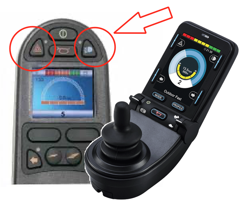
You need a compatible joystick with lighting controls for this process to work otherwise, even though everything is wired up, you won't be able to turn the lights on!
make sure you have lighting buttons on the older R-Net Color joystick
OR have the PJSM, or CJSM2
Setting things up:
There are 3 pin headers inside the ICS switchbox J5, J7, and J4 that are responsible for the lights
the drawings below are PINOUT diagrams.
NOT wiring schematics
The colored lines drawn across the pin headers are just showing labels for each pin's function.
Typically most people don't care about turn signals - so we'll focus on the headlights and tail lights.
———————————————————
theory of operation:
———————————————
The +24v power source for all lighting circuits is shared on pins 3, 7, 11, and 15
the system switches the negative side of each lighting circuit
there are 4 pin options for +24v you can mix/match them OR just pull everything from a single +24v pin
(though i recommend using at least 2 pins to spread out the load)
each lighting circuit is ACTUALLY switched with the negative connections
so pull power from any +24v pin, and then connect the negatives for each specific lighting circuit ya wanna control
I would recommend JUST using the 2 outside connectors with a single row of pins.
(J4, and J5)
Connector J7 can remain unused for this setup.
i haven't been able to source a proper fitting connector for it just yet.
Feel free to separate out your lights onto multiple headers
for example - a connector on J5 for Headlights, and another
connector on J4 for tail lights etc.. to spread out load on the pins
Ive used these connectors with good success -
OSEPP I2C Bus Cable (LS-CAB4P-08) - https://www.digikey.com/short/qp798jj5
you just have to slice off the latch on the side of the connector to make it fit into the header on the board.
then cut the cables in half - and each cable gives you 2 connectors!

Headlights:
PIN #3 for +24 volts
PIN #4 for NEGATIVE
Taillights:
PIN #15 for +24 volts
PIN #16 for NEGATIVE
if you want to install turn signals - they use use the same style of connectors you've already used for the headlights and tail lights - they will share the POWER +24v from PINS 3, and 15 that you used for the headlights/tail lights (assuming things are wired as shown above)
Right Signal-
PIN #3 for +24 volts
PIN #1 for NEGATIVE
Left Signal-
PIN #15 for +24 volts
PIN #13 for NEGATIVE

GOOD LUCK!!
for reference - here's the 2 ICS modules (old and new) side by side